In-Floor Heating Thermostat with Home Assistant and Shelly
One of my pet peeves is devices in the house that don’t track time accurately, or, don’t deal with Daylight Saving Time automatically. Well, I now have one fewer of those in my house, as I’ve replaced this “Easy Heat FTS-1” thermostat for electric in-floor heating with a Home Assistant powered thermostat.
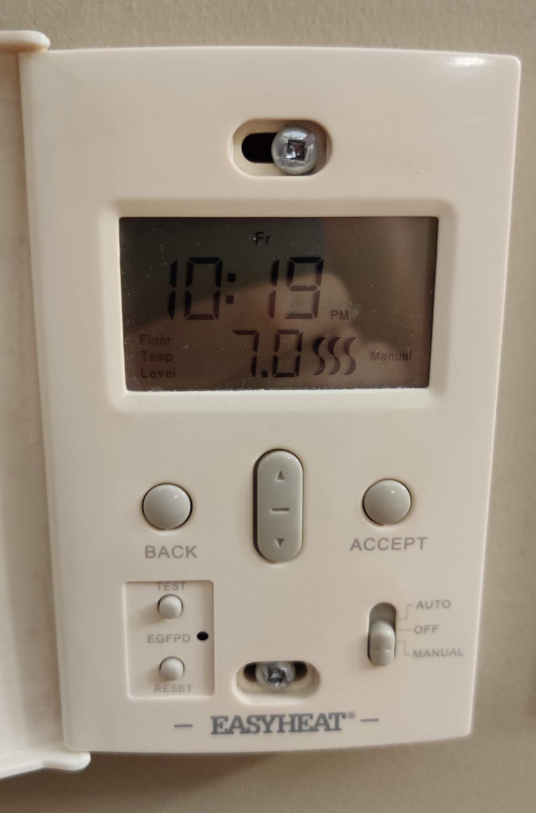
The original thermostat was a low-frills device. It allowed for two schedules to be configured, one for weekdays, and one for weekends, with the floor heat being set to four different temperatures at four different times. The temperatures were not measured in degrees, but rather, in unlabeled numbers from 1 to 10. The thermostat’s control interface was… better to not use it. And it lost time constantly, requiring manual adjustment every few months.
On the “backend”, the thermostat was a simple device. It had a 120V AC input for power, and a 120V AC output for the resistive heating of the floor. A thermistor input was used to measure the temperature of the floor; a thermistor is a resistor whose resistance changes with temperature.
So, things that needed to be done:
- Figure out what I was going to replace this with that could both control the 120V AC output and measure the thermistor input.
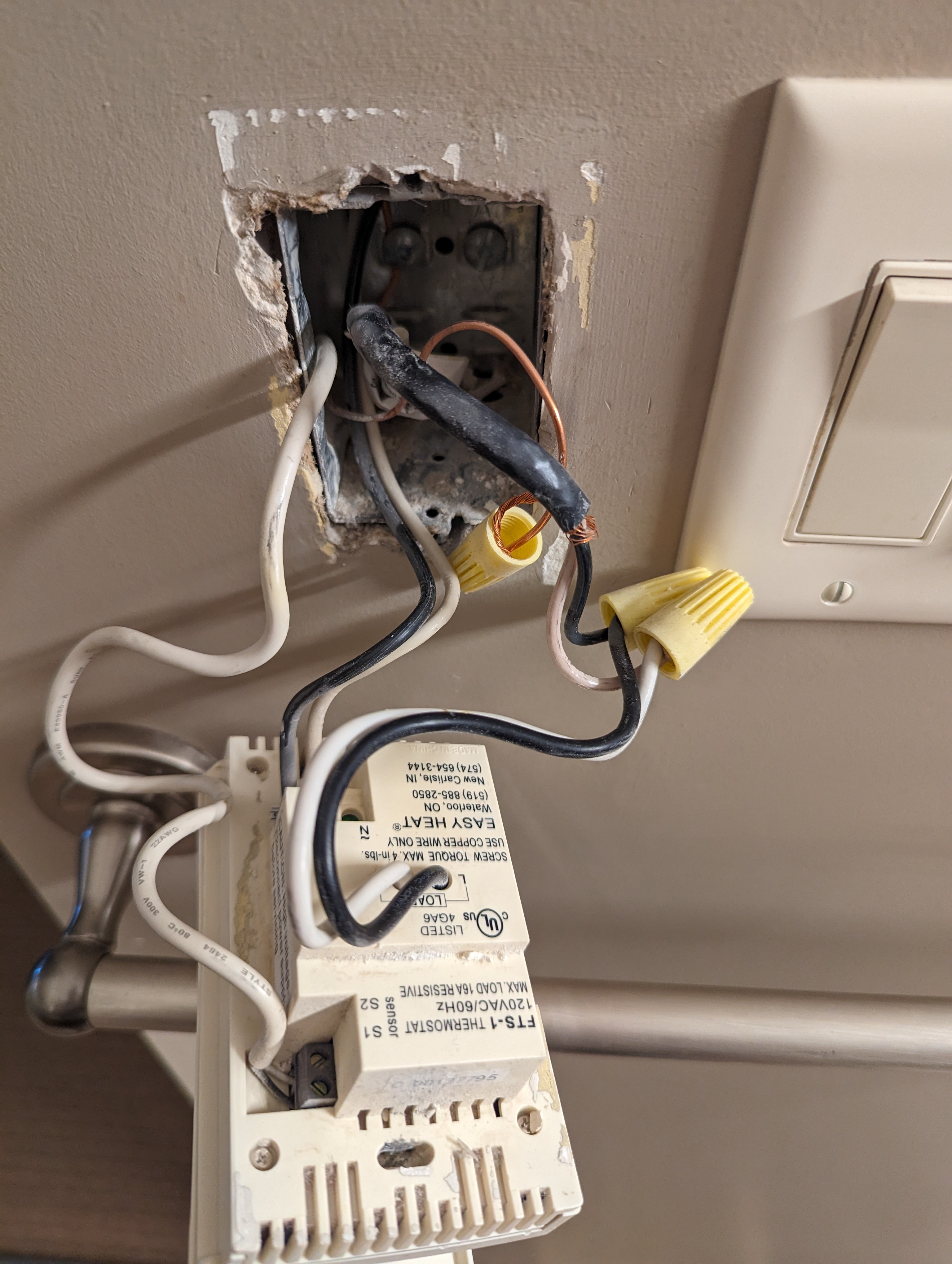
- Rip out the old thermostat and install and wire the new device.
- Integrate it with Home Assistant for remote control.
- Test that I could control the 120V AC output; at this point it was pretty much a win because a good scheduling configuration would be fine.
- Bonus points: figure out how to measure the thermistor input and integrate that into Home Assistant.
Hardware Hunt
My usual go-to for such projects would be an ESP32, flashed with ESPHome for its versatility and ease of use. Everything on my TODO list would be pretty straightforward to implement with it… but, usually when I work with an ESP32 I’m working with low-voltage DC, not high-voltage AC. I wanted something that was designed to be installed in a wall gang box, and that could handle the high-voltage AC safely. The resistive heating of the floor is about a 5A, 600W load; it would be easy to create a fire hazard if I didn’t do this right.
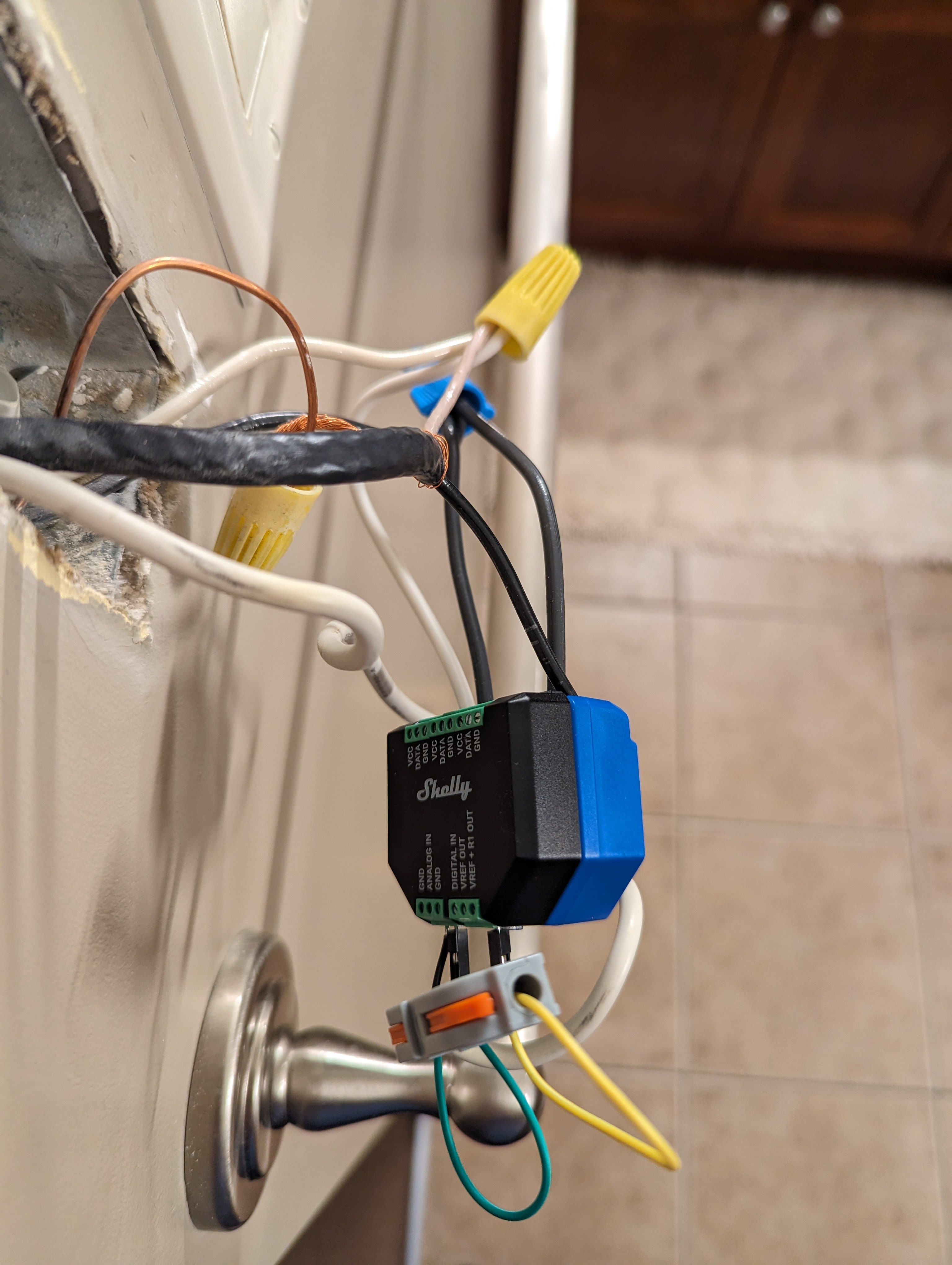
After some research, I opted for the Shelly Plus 1, a compact Wi-Fi & Bluetooth smart switch that’s designed precisely for such scenarios. I was originally thinking of going with a switch that I would flash with ESPHome… while I think that’s possible still with the Shelly Plus 1, I decided it might make more sense to just try it out-of-the-box first.
Additionally, to manage the temperature sensing with the thermistor, the Shelly Plus Add-on seemed like the perfect addition to the Plus 1. It’s obviously designed for this exact usage; it has a voltage divider circuit that’s perfect for reading the thermistor, and it snaps right onto the Plus 1.
Physical Installation
With the Shelly Plus 1 and Add-on in hand, the next step was installation.
The AC power wiring was quite straightforward; my input AC power was split between the “L” input to power the Shelly Plus 1, and the “I” input as an input for the relay. The output AC to the floor heating was wired to the “O” output of the relay. The neutrals from the input, the floor, and the Shelly Plus 1 were all connected together.
The thermistor was a bit more confusing. Shelly’s documentation for the Plus Add-on had a perfectly correct diagram, but, I screwed it up on the first pass due to my lack of familiarity with the voltage divider circuit. Once I figured it out, it was easy to fix:
- “VREF + R1 Out” was connected into a wire connector.
- One wire from the wire connector was connected to the “ANALOG IN”.
- The other wire from the wire connector was connected to the thermistor.
- The other end of the thermistor was connected to the “GND”.
Software Set-up
It’s hardly worth talking about the initial connection of the Shelly to Home Assistant; at least in my experience it was virtually automatic. I connected to the Shelly via its builtin Wi-Fi, and configured its connection to my home Wi-Fi. Home Assistant picked it up immediately, and I was able to control the relay output from Home Assistant.
At that point, I was able to write automations for Home Assistant to turn the floor heat on and off. With some timing settings, this probably would have been perfectly fine… but I was going for those bonus points.
Getting the thermistor read wasn’t exactly challenging… it was just undocumented. Which is really the primary reason why I thought I’d put this blog post up; because otherwise this was just a matter of reading the documentation and following the instructions.
So, here were the steps I took to get the thermistor read:
-
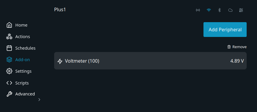
I configured the Shelly Plus Add-on as a voltmeter. This was done via the Shelly Web UI, which I accessed through my local Wi-Fi address, but it’s also possible to do it through the Shelly App. There aren’t a lot of settings involved here, so it’s not exactly complicated… but I wasn’t sure whether I should be using the “Analog Input” (since I’m wired to the “ANALOG IN”, you know), or the Voltmeter, and eventually figured out that the Voltmeter setting was what I needed for the next steps.
-
After 5-10 minutes, the Voltmeter began to appear in Home Assistant.
-
I configured a template sensor in Home Assistant to convert the voltage into a temperature. This was a bit of a challenge, because I didn’t have the thermistor’s specifications. What I did know was: the reference resistor in the Shelly Plus Add-on’s voltage divider circuit is 10k Ohm; the reference voltage was 10 V. Theoretically I either needed a B-calibration value and a reference temperature of the thermistor, or, to measure a few temperatures and calculate the appropriate calibration values. Well, I couldn’t find the right documentation, and changing the temperature of a floor by a huge amount and measuring it consistently is pretty impractical, so I chose reasonable approximate values for those, an extracted the NTC resistance to temperature calculations from ESPHome.
The values
ref_voltage,ref_resistorare used to calculate the resistence in the thermistor, and these values refer to the voltage on the circuit and the pulldown resistor in the Shelly Plus Add-On.The values
b_constant,ref_temp, andref_resistenceare used to calculate the temperature from the resistence, and refer to the B-calibration value of the thermistor, the reference temperature and reference resistance that the B-calibration value was measured at.template: - sensor: - name: "Bathroom Floor Temperature" unit_of_measurement: "°C" state: > {% set ref_voltage = 10 %} {% set ref_resistor = 10000 %} {% set b_constant = 3950 %} {% set ref_temp = 25 %} {% set ref_resistence = 10000 %} {% set resistence = ( (states.sensor.shellyplus1_b8d61a8aaa94_voltmeter.state|float) * ref_resistor) / (ref_voltage - (states.sensor.shellyplus1_b8d61a8aaa94_voltmeter.state|float)) %} {% set t0 = ref_temp + 273.15 %} {% set a = (1/t0)-(1/b_constant)*log(ref_resistence) %} {% set b = (1/b_constant) %} {% set c = 0 %} {% set lr = log(resistence) %} {% set v = a + (b * lr) + (c * lr * lr * lr) %} {% set temp = (1 / v) - 273.15 %} { temp|round(2) } -
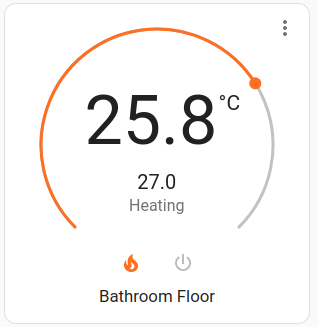
Then it was possible to configure a thermostat in Home Assistant based upon the temperature calculation, which turns the Shelly switch on and off based upon the temperature.
climate: - platform: generic_thermostat unique_id: bathroom_floor name: Bathroom Floor heater: switch.shellyplus1_b8d61a8aaa94_switch_0 ac_mode: false target_sensor: sensor.bathroom_floor_temperature -
And finally I’ve reached nirvana when I can add Home Assistant automations to turn the thermostat heating on and off at the right times.
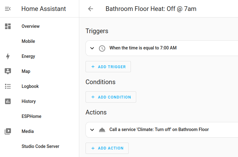
Now, the manual time adjustments are a thing of the past. My thermostat knows what time it is, all year round… and actually technically it doesn’t care because Home Assistant knows the same thing and is remotely controlling it.